
русский
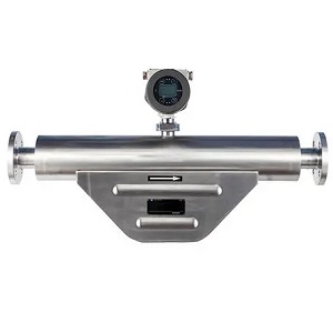
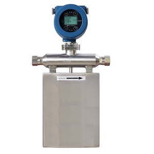
Прямое измерение массового расхода. ±0,1% до ±0,2% для жидкостей ±0,5% для газов Измерение плотности, температуры, давления Широкий диапазон регулирования до 100:1
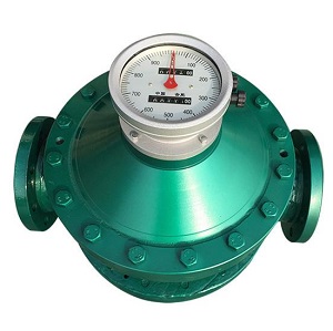
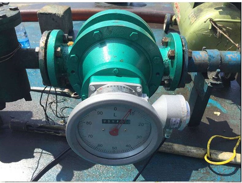
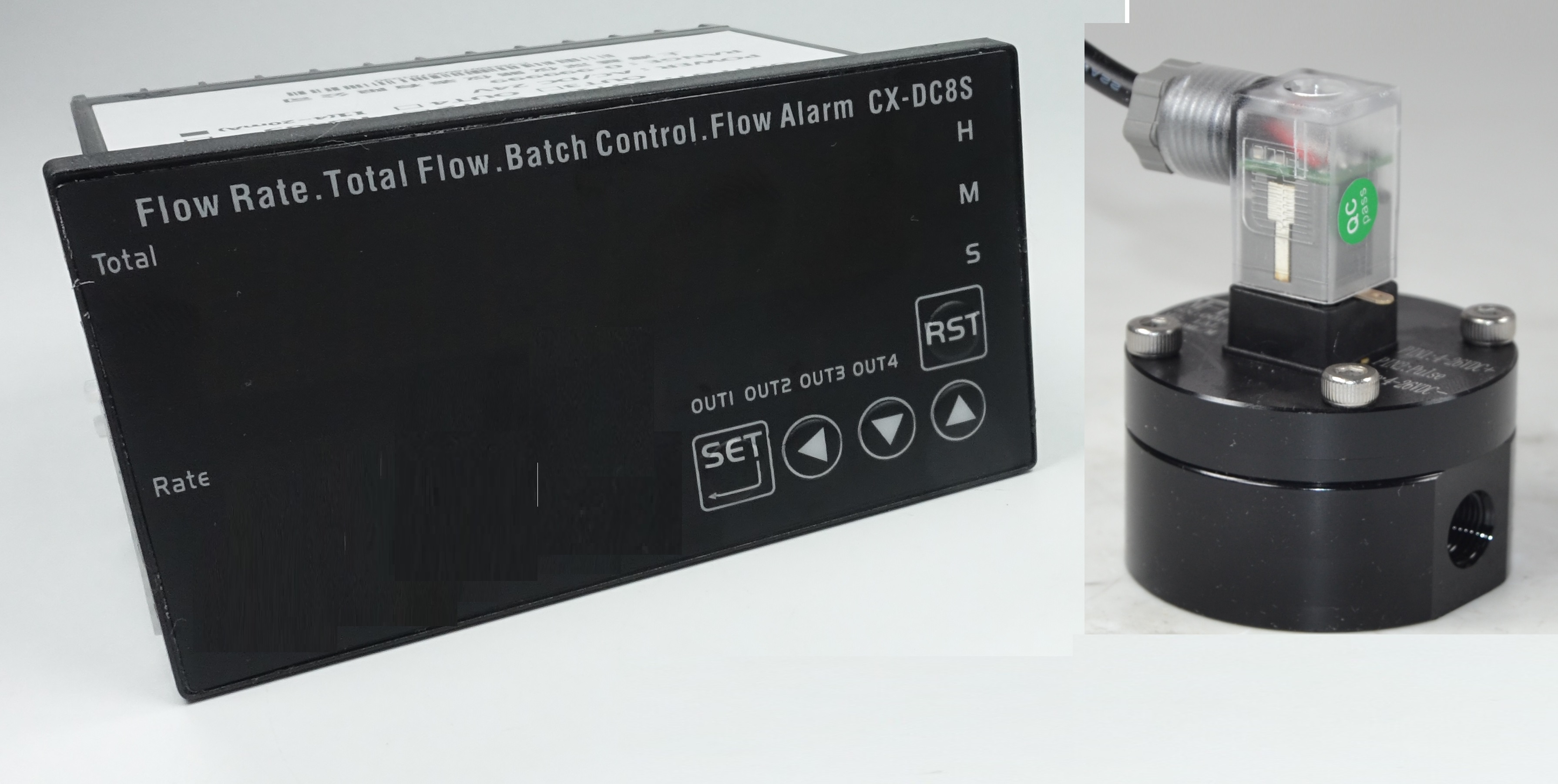
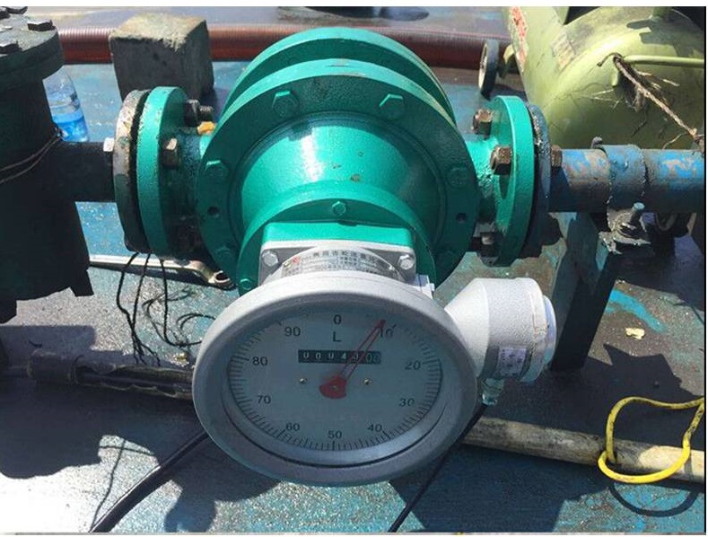
Почему объемные расходомеры прямого вытеснения могут использоваться для топлива и масел? Измерение объемного расхода топлива или масел относится к дизельному топливу, топливу на нефтяной основе, керосину, печному топливу для дома, реактивному топливу, диз
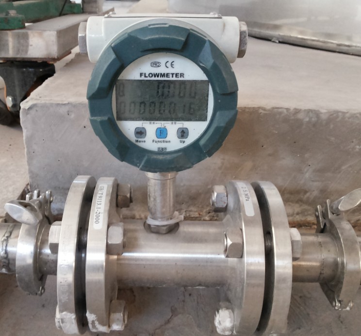
Расходомер мазута — это тип расходомера, специально разработанный для измерения массового расхода мазута в трубопроводе или технологической системе. Он широко используется в промышленности, например, в энергетике, морском транспорте и нефтегазодобыче.
Измерение расхода мазута, включая дистиллятный мазут, сырую нефть, остаточный мазут, биотопливо, датчик массового расхода бункерного топлива, устройство измерения расхода тяжелого мазута, сжигание ископаемого топлива, биодизель, судовое топливо. расходомеры топлива возобновляемый дизель Синтетическое топливо, а также масло используются в дизельных двигателях, промышленных котлах и печах, электростанциях и морских судах.
Не уверены, какой расходомер подходит для вашего типа топлива? Проверьте наш ассортимент. Полное руководство по расходомерам мазута Включая дизельное топливо, бензин и керосин.
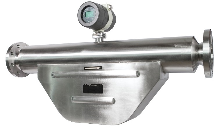
Кориолисовый расходомерэто идеальный выбор измерение расхода мазута Кориолисовый расходомер обычно состоит из трубки для измерения расхода и двух датчиков, которые измеряют силы Кориолиса, создаваемые жидкостью при ее протекании через трубку. Силы Кориолиса прямо пропорциональны массовому расходу мазута, что позволяет получать высокоточные и надежные измерения.
Расходомеры мазута способны измерять широкий диапазон скоростей потока, от очень низких до очень высоких, и могут работать с различными марками и вязкостями мазута. У нас есть множество типоразмеров датчиков массового расхода на выбор, диапазон расхода от 1 грамма/час до 1000 тонн/час. небольшой датчик расхода размеры от 1 мм до большой расходомер масла например, 10-дюймовые расходомеры масла. Они также рассчитаны на работу в суровых условиях, типичных для промышленных предприятий, таких как: датчик массового расхода масла при высоких температурах расходомер высокого давления, химический расходомер для коррозионных жидкостей, измерение расхода мазута под высоким давлением. измерение высоковязкого мазута .
Использование расходомеров мазута имеет важное значение для обеспечения эффективной и безопасной работы промышленных процессов, которые зависят от точного измерения расхода мазута. Предоставляя точные измерения расхода мазута в режиме реального времени, эти расходомеры помогают оптимизировать работу промышленных процессов или используются для целей коммерческого учета, сокращают отходы и потребление энергии, а также минимизируют риск аварий или отказов оборудования.
 |  |
 |  |
 |  |
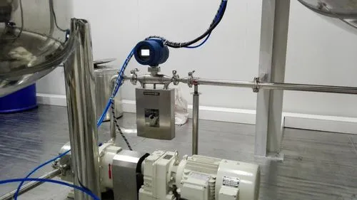
1. Кориолисовые расходомеры работают по принципу вибрации. Поэтому желательно, чтобы в месте установки не было вибрации. Надежная опора монтажных трубопроводов для кориолисовых расходомеров очень важна. Если вибрацию нельзя игнорировать, рекомендуется использовать гибкое трубчатое соединение. Соединительные трубопроводы и расходомеры должны располагаться на одной оси. Не следует прилагать дополнительную силу к расходомерам, иначе точность измерений может снизиться.
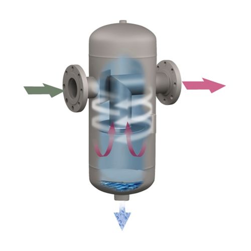
2. Если процентное содержание газа в измеряемом мазуте высокое, то необходимо установить газожидкостный сепаратор на входе кориолисовых расходомеров.
3. The throttle devices, for example the flow control valves should be installed on the outlet of the mass flow meters.
4. The mass flow meters should be installed away from the outlet of the pumps. Especially for the Dual pumps, if the installation distance is too close, then the measured flow rate could be affected, which is fluctuated.
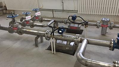
5. If measuring high temperature oil or it is required to keep warm of the measured oil, Please keep distance between the inner tubes of the heating jackets or the heating tubes with the housings of the sensor. We factory also provide the heating jackets along with the mass flow meters, for example the heating jackets for steam or transfer oil. Please specify that you need heating jacket for flow meters to silverinstruments.com
6. The measured oil should be on the suitable flowing status. If under the local environment the flowing status of the liquids is not suitable, then it is suggested to improve with other methods, for example to modify the temperature of the liquids ( increasing / decreasing the temperature of the fuel oil to make sure the measured liquids are in the proper flowing status.
7. Installation direction: please make sure the flowing direction of fuel oil should be the same with the direction marks on the nameplates of the coriolis mass flow meters. Otherwise the accuracy of the mass flow meters could be affected.
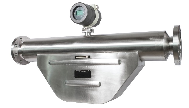
8. Please make sure the series numbers of the mass flow transmitters and the fuel oil flow sensors are one -to-one corresponded to each other. It cannot be easily changed. Otherwise the accuracy of the mass flow meters could be affected.
9. Если расходомеры мазута установлены на открытом воздухе, лучше всего установить для них защитные кожухи от дождя. Убедитесь, что передняя и задняя крышки расходомеров плотно закрыты. Также убедитесь, что электрический интерфейс хорошо герметизирован, чтобы предотвратить попадание воды внутрь датчиков.
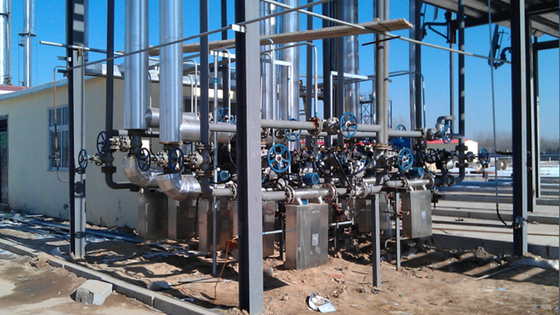
10. Рекомендуется использовать нормальный рабочий расход, превышающий 1/3 стандартного диапазона расхода расходомеров. Также рекомендуется, чтобы фактический минимальный расход был выше, чем 1/10 стандартного диапазона расхода расходомеров. В случае особых обстоятельств, пожалуйста, свяжитесь с silverinstruments.com. Поскольку у нас есть собственная команда разработчиков, мы можем изготовить расходомеры на заказ в соответствии с вашими особыми требованиями, чтобы гарантировать соответствие потребностям пользователей в данном диапазоне применения.
The integration of the Coriolis Mass Flow Meter has been connected and installed before the delivery.
The separated transmitter and the sensor are connected by the special connection cables and connectors. If the separation installation of the transmitter and the sensor is required, please contact us in advance before placing the order. The maximum length should not exceed 300m.
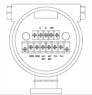
24V + \– 24VDC Power Supply (Current should not less than 500mA)
Fo + \– Frequency Output (instantaneous mass flow or volume flow)
mA + \– Current Output (instantaneous flow or density optional)
(HART + \–) HART
485A \485B RS-485 Communication (Baud Rate: “9600”, Address: “1”)
The zero point calibration is required after the Coriolis Mass Flow Meter installation. Please fill in large amount of measured medium for 10 minutes before the zero point calibration.
The zero point calibration is used to provide the benchmark of the flow measurement. The zero point must be processed after the first-time calibration or re-installation. Please make sure firstly it is required to turn off the stop valve at the exit of the mass flow meter, and then turn off the stop valve at the entrance. And make sure the liquid fulfilled the sensor is comparatively at the stationary state during the calibration. The detailed operation methods are as below video shows:
Поиск и устранение неисправностей кориолисового расходомера
Symptom | Failure Reason | Solution |
No display | Check whether is 24VDC power supply is normal | Make sure 24VDC is working normally |
Fluctuation of flow rate measured is large | Whether there’s strong vibration of the line connected to the sensor | Adding support or switching to hose connection |
Could not enter the measuring interface after the boot | Do not connect with the sensor | Check the cables, and make sure they are connected to the sensor properly |
Zero Point Drift is large | The installation of the sensor has stress | The connecting line and the sensor interfaces should be at the same axis |
Attention: (0-10)KHz and (4-20)mA output signal is already with the power supply. It is forbidden to connect with other external power sources. Otherwise the damage of the mass flow meter could be caused.
Мы свяжемся с вами в течение 24 часов..